Kamis, 07 April 2011

ALAT PENGUSIR TIKUS

Mice are wild animals and very annoying. "Action bawdy" it could be all kinds ranging from pooping everywhere, rummaging through closets and warehouses, spread diseases (plague), and so on. Just always make a scene! One alternative to overcome this is to use an electronic mouse repellent. In addition to environmentally friendly, this tool can also be used as a hobby and learning the distribution of electronics.

To drive these rats disorders, you can create an electronic circuit as shown below. This circuit will generate a 50Khz frequency disturbing enough for a mouse but you do not have worried because you will not hear it. This series is guaranteed by the rats would run because his ears will feel pain from the vibration signal ferkuensi.

http://elektroarea.blogspot.com/
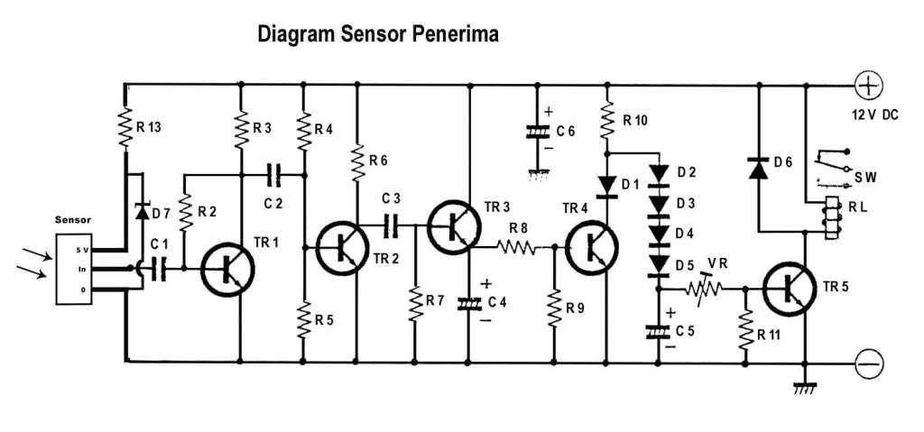
Skema Rangkain Pengusir Tikus

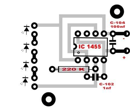
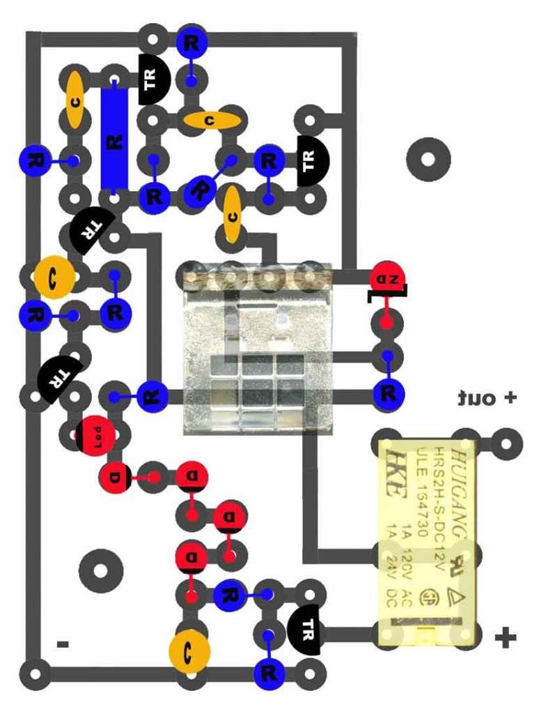
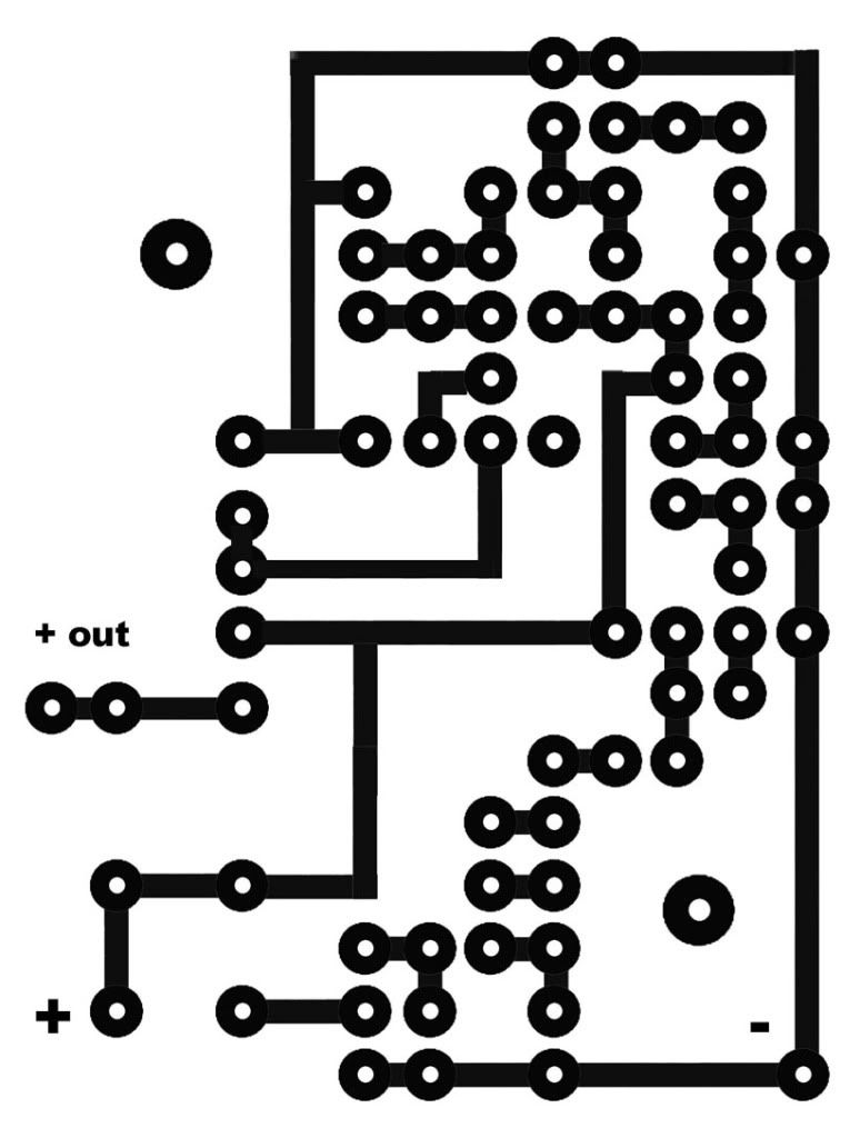
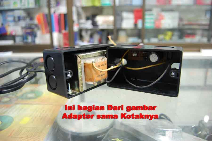
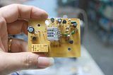
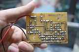
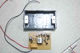
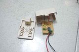
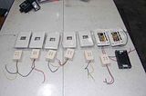
Electronic components on the need to build a mouse repellent electronic circuit is not much, quite cheap and readily available at electronics stores. Electronic circuit scheme can be viewed directly on the image above. The circuit can be built on a dot matrix or PCB layout to make it with plain munggunakan PCB. Within a few days after the installation of this device (a continuous) will be visible results. The mouse and his relatives would be taken off some where and rumahpun rid of most annoying animals.


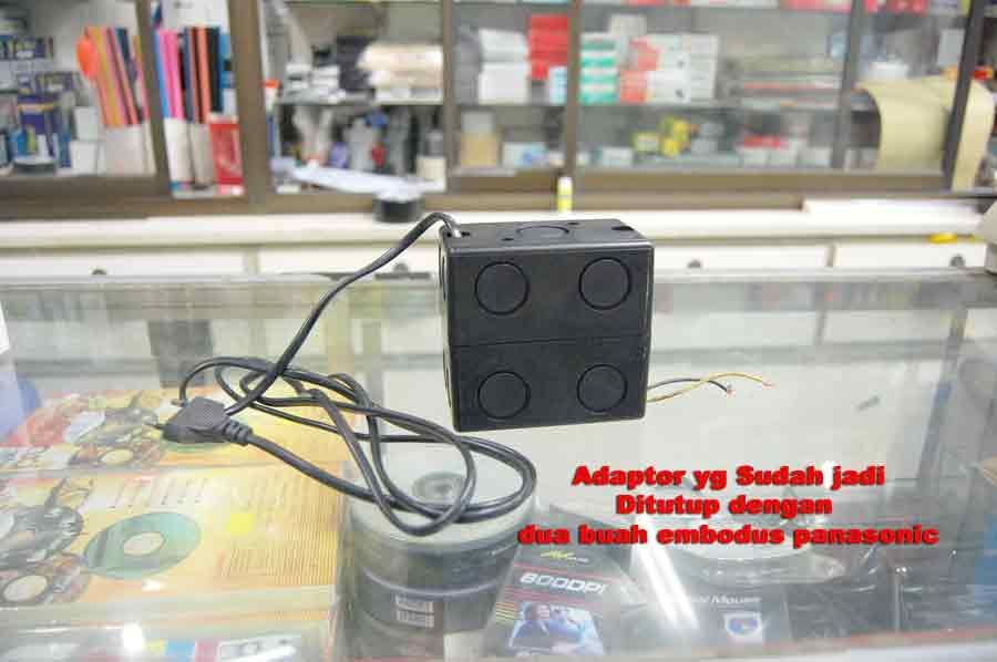
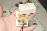
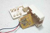
Heart of electronic rat repellent circuit IC 555 is already very popular, cheap and versatile. For maximum results use the loudspeaker from the PIEZO tweeter speakers electric or funnel shape. Electronic rat repellent is effective for rooms up to 200 m 2 area from the right placement. This circuit is placed in the corner of the room so that his frequency noise can be spread across the room without a hitch. Turn on continuously to keep the rats do not come back, do not worry about the electricity consumption for electrical power needed is low enough, is still greater watt/220 light bulb 5 volts.

ALAT PENGUSIR NYAMUK


Saturday, August 15, 2009

Rangkaian Pengusir Nyamuk

Sponsored Links:
This is a circuit diagram of an ultrasonic mosquito repeller (pengusi yamuk). The circuit is based on the theory that insects like mosquito can be repelled by using sound frequencies in the ultrasonic (above 20KHz) range. The circuit is nothing but a PLL IC CMOS 4047 wired as an oscillator working at 22KHz. A complementary symmetry amplifier consisting of four transistor is used to amplify the sound. Speaker Piezo buzzer converts the output of amplifier to ultrasonic sound that can be heard by the insects.

Rangkaian Pengusir Nyamuk
Skema Rangkaian Pengusir Nyamuk

The circuit can be powered from 12V DC. The buzzer can be any general purpose piezo buzzer.

Description IC CD4047B

IC CD4047B is capable of operating in either the monostable or astable mode. It requires an external capacitor (between pins 1 and 3) and an external resistor (between pins 2 and 3) to determine the output pulse width in the monostable mode, and the output frequency in the astable mode. Astable operation is enabled by a high level on the astable input or low level on the astable input. The output frequency (at 50% duty cycle) at Q and Q outputs is determined by the timing components. A frequency twice that of Q is available at the Oscillator Output; a 50% duty cycle is not guaranteed. Monostable operation is obtained when the device is triggered by low-to-high transition at a trigger input or high-tolow transition at b trigger input. The device can be retriggered by applying a simultaneous low-to-high transition to
both the a trigger and retrigger inputs. A high level on Reset input resets the outputs Q to low, Q to high.

Lay out IC CD4047B
Block and Connection Diagrams IC CD4047B

IC CD4047B Applications

Frequency discriminators
Timing circuits
Time-delay applications
Envelope detection
Frequency multiplication
Frequency division

SENSOR ALAT PRAKTIS ANTI MALING

mbuat Sensor Anti Maling

Posted by sakuraaba pada April 8, 2009
Pengalaman saya waktu rumah saya Kemalingan sangat menggelikan.
Karena Saya Sering iseng Dengan Mengutak-atik Bahan Elektronik, saya pun membuat suatu rangkaian anti maling yg cukup unik. Rangkaian ini bekerja berdasarkan Sensor, terdiri dari 2 bagian.
Yaitu Bagian Pemancar Infrared Dan Bagian Penerima, jika Sensor tersebut di lewati/terhalang benda/manusia maka sensor tersebut akan berbunyi. Pengalaman saya waktu rumah saya Kemalingan sangat menggelikan. Waktu itu maling sudah masuk kerumah, saat melintasi sensor alarm pun berbunyi, Malingnya kesibukan mencabut cok listrik disekitarnya tetapi alarm tidak mau mati juga. Akhirnya terperogok oleh orang tua saya, Malingnya langsung melarikan diri. Sementara dalam waktu yg sama Orangtua Saya pun Lari masuk kekamar Dan mengunci kamar sambil berteriak maling.
Orang Tua Saya Lari Karena Tidak tahu berapa banyak maling yg masuk kerumah, jika satu masih bisa dilawan tetapi kalau ada dua atau tiga bagaimana melawannya ( pikir orang tua saya ) lebih baik lari mencari tempat yg aman.
Beruntung Sensor yg saya pasang sangat berguna. Jika Teman-teman Mau membuatnya sendiri nanti saya posting rangkaiannya. Gampang kok Cara membuatnya. Modalnya tidak sampai Rp.100.000 jika merakit sendiri.
Adapun komponen yg diperlukan adalah sebagai berikut :
Gambar sensor pemancar dilihat dari atas
Gambar sensor pemancar dilihat dari bawah
Komponen Rangkaian Pemancar
R1………………………….220k
C1……………………..….1 Kpf
C2………………………100 Kpf
IC……………………..MC-1455
D1,2,3,4………………Infra Red
Gambar Sensor Penerima Dilihat dari atas
Gambar Sensor Penerima dilihat daribawa
Komponen Rangkaian Penerima
R1………………………..220k
R2………………..….….470k
R3…………………..…….33k
R4, 7…………………….180k
R5, 11………………….….47k
R6………………………….22k
R8…………….…..470 ohm
R9, 10……………………….1k
R12 ……………………….4.7k
R13………………………….1 K
C1………………………4,7Kpf
C2……………………….10Kpf
C3……………..……….33Kpf
C4…………..……………10 uf
C5, 6………………….100 uf
Tr1, 2, 3, 4……….…..C828
Tr5………………….….C1815
D1…………………….…..LED
D2, 3, 4, 5, 6……..1N4148
D7………………….Zd 5.1 V
Relay…………….….6 V / 12 V
Sensor …………..… TV/Vcd
Ini adalah gambar yg sudah jadi
yang saya penggang di tangan adalah bagian dari penerima dilihat dari depan dan dari belakang.
gambar dibawah ini  adalah rangkaian penerima dan tempatnya.
ini adalah gambar dari rangkaian pemancar infra red yg sudah jadi
dan yg terakhir ini adalah gambar rangkaian yg sudah siap di pasang.
banyak ya !!  maklum dapat orderan buat pasang di rumah wallet.
sampai disini dahulu ya…
sorry kalau ada yg menunggu terlalu lama update yg terbaru dari saya.  Soalnya terlalu sibuk bekerja.
Selamat Mencoba !!!  jika tidak mengerti silakan tinggalkan pesan atau saran dari pembaca.
Mudah-mudahan gue balas…!!

PEMANCAR FM

Selamat datang...
Kami dari solo antena adalah bengkel perakitan / pembuatan peralatan - peralatan untuk pemancar radio dan tv broadcast.
Produksi Kami :


  • PEMANCAR FM
  • PEMANCAR TV
  • ANTENA DOUBLE RING
  • ANTENA TYPE SIRA
  • ANTENA YAGI
  • ANTENA SINGLE RING
  • POWER DEVIDER,
  • STL (STUDIO TRANSMITTER LINK ) VHF /UHF
  • KONEKTOR FLANGE 5/8,7/8 1 5/8
  • TOWER TRIANGEL


omb 3   
12 tabung1
LINK

RVR
dBbroadcast
OMB
PLL SCEMATIC
DIGITAL PLL SCHEMATIC
Bisnis Internet
DATA SHEET CATALOG
FREKWENSI COUNTER SCHEMATIC

PEMANCAR TV MINI UHF/VHF

Skema Pemancar TV Mini
http://www.reject.org/tsd/liz/gbppr/mc1374_tv_tx.png
Kutipan dari :

Twitter Delicious Facebook Digg Stumbleupon Favorites More

 
Design by Free WordPress Themes | Bloggerized by Lasantha - Premium Blogger Themes | Modern Warfare 3